
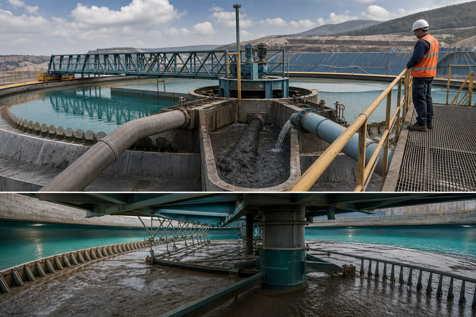
Define the feedwell duty
The feedwell must dissipate incoming momentum, distribute slurry and support flocculation before material enters the settling zone. Record flow, mass solids, particle distribution, feed density and the current dilution arrangement.
Include upstream pumps, cyclones and reagent additions because they set the shear and surface condition arriving at the feedwell.
Calculate dilution on a mass balance
State dilution water, feed flow and solids basis rather than a valve position. Confirm whether the water is fresh, overflow recycle or another stream, and measure its chemistry. Dilution changes local solids concentration and contact conditions.
It also changes hydraulic loading, so more dilution is not automatically better.
Place polymer for distribution
Prepare fully hydrated stock and add secondary dilution when needed for coverage. Compare addition to the feed pipe, dilution stream or staged points while keeping active dose constant. Observe whether intense mixing occurs before or after adsorption.
A concentrated ribbon can form a few giant flocs while leaving much of the feed unconditioned.
Use cylinder and pilot evidence carefully
Bench settling narrows grade and dose, but wall effects and simplified mixing do not reproduce a plant feedwell. Include controlled shear, measure clarity and compacted volume, and carry several candidates to a monitored plant step.
Do not translate a jar dose without reconciling dry-solids flow.
Read the whole thickener
Track overflow turbidity or solids, bed level, underflow density, rake torque, pump behavior and throughput after sufficient residence. A transient clear overflow can occur before the bed reflects the new condition.
Keep feed and mechanical settings stable during each comparison.
Approve a resilient window
Repeat the selected dilution and polymer range across normal and difficult feed. Set operating limits for feed solids, dilution and active dose with clear response indicators.
Review water balance and underflow handling before making a high-dilution condition permanent.
Survey the feedwell before changing chemistry
Record feed-pipe diameter, entry direction, available pressure, dilution points, polymer lances, shelf or vane geometry and visible short-circuit paths. Note whether the feedwell is submerged and whether entrained air or froth interferes with distribution.
Review maintenance condition. Blocked dilution nozzles, damaged internals or asymmetric feed can create a response that no polymer adjustment can fully correct.
Calculate solids flux and hydraulic loading
Express feed as dry-solids mass per area and water flow per area using verified plant measurements. Track both when dilution changes because lower local concentration may improve flocculation while higher total water flow increases overflow demand.
Relate the calculation to the current bottleneck. A plant limited by overflow clarity may accept a different dilution balance from one limited by underflow density or rake torque.
Plan staged injection trials
Compare one well-distributed point with a staged arrangement only when the feedwell can support both safely. Hold total active polymer constant and document the fraction at each point, stock concentration and dilution water.
Allow stable residence before sampling. A staged system is justified only when it improves measured separation or operating range enough to offset added hardware and control complexity.
Use bed and underflow data
Track bed level trend, interface stability, underflow density, yield stress or pump load where available, and rake torque. A fast surface response can coincide with a loose bed that reduces effective capacity.
Take underflow samples at consistent withdrawal conditions. Changing pump speed during a polymer step can alter bed inventory and obscure the chemical result.
Create a feedwell control envelope
Define ranges for feed solids, feed flow, dilution ratio, active polymer dose and water chemistry. Link each limit to an observable response such as overflow turbidity, bed rise, torque or underflow density.
Retain the trial sequence, residence assumptions and mass balance. Future ore or water changes can then be compared with the qualified envelope before a new product campaign is started.
Place matched plant sampling points
Collect feed before dilution, dilution water, overflow and underflow during one stable test period. When safe plant access permits, note feedwell appearance and surface floc distribution. Match every sample to feed flow, dry solids, polymer flow, dilution and equipment readings.
Samples collected at different residence stages can describe different polymer conditions. Use the thickener inventory and hydraulic delay to decide when a step has reached each location.
Review the result after sustained operation
Confirm the selected window over a shift or other meaningful period that includes normal feed movement. Reconcile dry-solids throughput, polymer inventory, overflow return, underflow withdrawal and torque. A short successful step can consume an existing stable bed without proving the new condition maintains it.
Retain trends and event notes so later bed rise or clarity loss can be compared with feed, dilution and polymer changes.